Flexible Circuit Boards for Underwater Applications
Flexible Circuit Boards for Underwater
When it comes to designing electronic devices and hardware, manufacturers often use rigid boards that can withstand a certain amount of pressure and movement. However, in many cases, the equipment needs to be able to endure extremely rapid movement and extreme conditions for extended periods of time. That’s where flexible circuit boards come in.
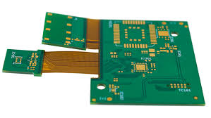
A flexible circuit board is like a rigid PCB in that it contains copper tracing communication pathways, but it’s made with a polymer substrate instead of fiberglass-reinforced epoxy. This allows for the flex circuit to be more bendable and light, opening up more design possibilities for electronics in constrained spaces.
Flex circuits can also offer improved performance over traditional rigid board designs due to their smaller size and increased flexibility. They can be used as an alternative to hand wiring or soldering, which not only saves time but eliminates the potential for errors and failures. Moreover, they can provide a better thermal path for heat to dissipate from the component, which is especially important in high-temperature applications.
Flexible Circuit Boards for Underwater Applications
In addition to their ability to withstand a variety of environmental conditions, flex circuits can support different types of connectors and components that can be easily placed using crimped contacts, ZIF connectors or direct soldering. This allows designers to create a more complex device or product and reduces the overall cost of manufacturing.
Conductor materials for a flex circuit can be either copper foil or conductive coatings. Compared to copper foil, conductive coatings are more affordable, but they have lower conductivity. If a flex circuit is going to be subjected to repeated creasing or movement, it’s best to choose higher-grade Rolled Annealed (RA) copper foil. This is more resistant to fatigue cracking and work hardening than standard ED copper foil.
While a flex circuit can be made in many sizes and shapes, the most common design is a single-layer flex circuit. A single-layer flex PCB has one layer of polyimide and thin copper, which is etched through a layer of adhesive-based PolyImide coverlay that is pre-punched to expose the copper. The copper is then plated with tin or soft gold for additional durability and electrical conductivity.
A single-layer flex PCB can be made in multiple thicknesses and layers, but the most popular options are 2.0 mil and 3.0 mil. The thickness of the flex PCB affects how much it can flex and where it’s capable of bending. The thickness is also determined by the number of layers and the type of conductor material.
The flex PCB’s design is crucial for its waterproof characteristics. It should have uniform coverage of the waterproofing material, with no thin spots or gaps. Visual inspection is the best way to ensure proper coverage. The waterproofing material can be applied with an additive or subtractive process, depending on the device’s needs. In either case, it’s important to have the right tools to create a quality flex circuit. Using the comprehensive CAD features and automated drawing tools in Altium Designer + Draftsman can help you design the right flex PCB for your unique application.